Introduction
Unified Modeling Language or UML is a standardized graphical language developed by the Object Management Group (OMG) to visualize, specify, communicate, construct, and document software systems. First introduced in January 1997 with version 1.0, this tutorial focuses on UML version 2.5.1, which comprises 14 diagrams categorized into two main types.
Structural Diagrams
Structural diagrams depict the static architecture of a system’s objects irrespective of time. They represent the significant concepts within a system and can include abstract ideas, real-world entities, and implementation details. While structural diagrams don’t illustrate dynamic behaviours, they may indicate relationships with the behaviours of classifiers within the diagrams.
Behavioural Diagrams
Behavioural diagrams capture the dynamic interactions and behaviours of a system’s objects, including methods, collaborations, activities, and state changes. Interaction diagrams focus on the communication between objects within a system. They provide a detailed view of how objects interact through message exchanges over time, crucial for modeling and understanding use cases, workflows, and functional requirements.
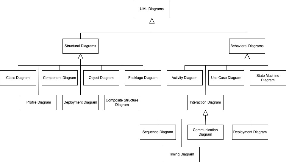
Taxonomy of UML Diagrams
In order to better understand the organization and categorization of UML diagrams, the following illustration provides a visual representation of the types of UML diagrams.
Prerequisites
No specific skills are required to start. However, a general understanding of the software development process and object-oriented programming is beneficial.